- 您现在的位置:买卖IC网 > Sheet目录368 > VPROG-1-S-LQFP48 (FTDI, Future Technology Devices International Ltd)VPROG-1 SOCKET/ADAPTER 48-LQFP
Document Reference No.: FT_000059
VPROG-1 Vinculum Host Controller Programmer Datasheet Version 1.00
Clearance No.: FTDI# 42
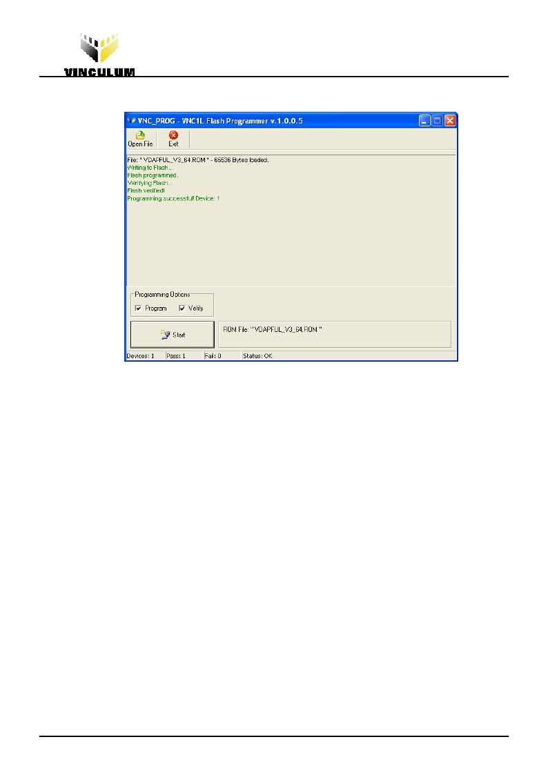
6. When programming is complete, check that the PASS LED is ON. This indicates that
programming is complete. The user interface, when complete, is shown in Figure 3.8:
Figure 3.8 VPROG-1 Completion of Programming VNC1L-1A
7. To repeat the process, either press the PROGRAM button on the VPROG-1 module or
the “START” button on the PC user interface.
8. When complete, the Vinculum host controller device can then be removed from the
VPROG-1-S-LQFP48 socket.
3.6 Programming VDIP Vinculum VNC1L-1A Evaluation Boards
The VDIP modules allow users to quickly prototype using the Vinculum host controller device,
VNC1L-1A.
The modules provide a Vinculum VNC1L-1A device plus a number of USB host connections.
VDIP1 has 1 USB host. VDIP2 has 2 USB hosts. The VDIP1 module is interfaced to via a 24 pin
DIP connector. The VDIP2 is interfaced to via a 40 pin DIP connector.
To program a VDIP module, then the VPROG-1-S-ZiF40 adaptor should be fitted. The VDIP1
connects to the VPROG-1-S-ZIF40 as shown in Section 3.6.1. The VDIP2 connects to the
VPROG-1-S-ZIF40 as shown in Section 3.6.2.
Programming the modules follows the same steps shown for programming the host controller
devices shown in Section 3.5.
3.6.1
Connecting VDIP1 to the VPROG-1-S-ZIF40
The VDIP1 connects to the VPROG-1 via the VPROG-1-S-ZIF40 adaptor. The VDIP1 has 24 pins
and should be connected as shown in the following Figure 3.9
Copyright ? Future Technology Devices International Limited
9
发布紧急采购,3分钟左右您将得到回复。
相关PDF资料
W19B320ATT7H
IC FLASH 32MBIT 70NS 48TSOP
W19B320BTT7H
IC FLASH 32MBIT 70NS 48TSOP
W25Q128BVEIG
IC SPI FLASH 128MBIT 8WSON
W25Q16BVSFIG
IC SPI FLASH 16MBIT 16SOIC
W25Q16CVSFIG
IC SPI FLASH 16MBIT 16SOIC
W25Q16DWSFIG
IC FLASH SPI 16MBIT 16SOIC
W25Q16VSFIG
IC FLASH 16MBIT 80MHZ 16SOIC
W25Q32BVZPIG
IC SPI FLASH 32MBIT 8WSON
相关代理商/技术参数
VPROG-1-S-ZIF40
功能描述:界面开发工具 Adapter for VPROG-1 ZIF-40 for VDIP1&2 RoHS:否 制造商:Bourns 产品:Evaluation Boards 类型:RS-485 工具用于评估:ADM3485E 接口类型:RS-485 工作电源电压:3.3 V
VPS
功能描述:开关配件 PANEL SEAL BLACK
RoHS:否 制造商:C&K Components 类型:Cap 用于:Pushbutton Switches 设计目的:
VPS 510-B
功能描述:测试探头 Voltage Probe Set 10:1, 500 MHz-Blue
RoHS:否 制造商:Teledyne LeCroy 设备类型:Passive Probes 带宽:500 MHz 尖端类型: 长度:1.3 mm 颜色:Black 电压额定值: 电流额定值:
VPS 510-G
功能描述:测试探头 Voltage Probe Set 10:1, 500 MHz-Grey
RoHS:否 制造商:Teledyne LeCroy 设备类型:Passive Probes 带宽:500 MHz 尖端类型: 长度:1.3 mm 颜色:Black 电压额定值: 电流额定值:
VPS 510-R
功能描述:测试探头 Voltage Probe Set 10:1, 500 MHz-Red
RoHS:否 制造商:Teledyne LeCroy 设备类型:Passive Probes 带宽:500 MHz 尖端类型: 长度:1.3 mm 颜色:Black 电压额定值: 电流额定值:
VPS 510-V
功能描述:测试探头 Voltage Probe Set 10:1, 500 MHz-Green
RoHS:否 制造商:Teledyne LeCroy 设备类型:Passive Probes 带宽:500 MHz 尖端类型: 长度:1.3 mm 颜色:Black 电压额定值: 电流额定值:
VPS PANEL SEAL BLACK
制造商:Carling Technologies 功能描述:HARDWARE - Bulk
VPS PANEL SEAL, BLACK
制造商:Carling Technologies 功能描述:HARDWARE
